Introducing the Takaya Electrical Attributes Editor
In version 10.1, Test Expert has introduced a new, Takaya-specific, workflow menu. This workflow includes a new Electrical Attributes Wizard and simplified dialogs specifically for Takaya flying probe testers.
In the video, we highlight a major feature, the Electrical Attributes Editor, which provides a simple, tab-based, consolidated user interface for setting all attributes required for Takaya programs.
Editor Layout
The interface is grouped logically into five tabs:
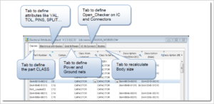
- Classes
- Electrical Attributes
- Grid & Power
- IC & Connect
- Bodies
Tab 1: Classes
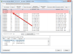
If a part number is missing some required data, it will be highlighted in RED in the table. Notice in the image that reference PT1 is highlighted in red. If you view the Error/Warning field, PT1 has no CLASS defined. When the class is updated, the red highlight goes away, and the component data is complete.
Tab 2: Electrical Attributes Tab
The Electrical Attributes tab validates the Takaya attributes:
VAL, TOL, NTOL, PINS, SPLIT, TYPE, SPEED, HEIGHT
The application checks the data for missing or inconsistent information and will highlight the inconsistencies in RED. These errors also are listed in the « Error/Warning » column.
Component Type Lists
To add the Takaya type [TYP=] statement users will select the Type column dropdown menu. The type dropdown list is dynamic based on the Class of the Component.
For example, selecting the dropdown for a capacitor shows several capacitor types for use by Takaya. Select your desired type.
Split & Pins

Defining a component split or critical device pins in Test Expert is an easy task with the new interface.
For example, to define a PINS attribute we select D7 in the above image and, in the lower left table, right click on the Pin Name column to set the specific pin type – Anode, Cathode or N/C.
Tab 3: Ground & Power

The GND & Power Tab allows users to define the names of Power and Ground nets in the job. The defaults from the configuration file are loaded into the upper window – V3.3 and GND in the above example, and other candidates are in the lower window. These can be added with a right click.
Tab 4: IC & Connect

The IC & Connection tab is used to manage the test TYPE only on ICs and Connectors, especially for the open checker test. Simply select the IC and the appropriate type from the TYPE drop down.
Tab 5: Bodies
In the Bodies Tab users are able to adjust the component outline. Often body outlines are defined incorrectly in CAD and may cover probeable pins. This is similar to the Edit Shape function in the Job Data Editor.
Watch the video to see the features in greater detail.
If you still have questions or would like to take a closer look at Test Expert, give us a call at 855-642-2848 or send us an email.
Thanks for watching!
